All fingers are intact and at same level. That is promising. Your photos are still private. Perhaps better uploading to this site.
-
-
Today I removed the clutch (by the engine). The key used was a annular elbow (http://www.clubafaceri.ro/52532/chei...m-2728775.html) adjusted the grinder.
We gave him the floor (chipboard above) with anger - not opened .
I gave WD40 - nothing.
Trying for a press extract bearings adapted to.
We probably forgot something.Comment
-
You got to be pretty determined. Hold flywheel with clutch facing floor. Bang flywheel forcefully against board which must be on a solid concrete. You may try banging edge of flywheel against the board at different angles. Mine came out instantly but then I've done it a few times.Originally posted by mottofreee View Post
Comment
-
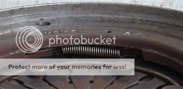
I've just opened out my clutch to have a good look at it and to replace a broken cam ring pull spring.
Here is how the Sachs automatic wear compensating mechanism works:
There are two cam rings. One is fixed to pressure plate housing and will not rotate. The other cam ring, which is nearest to pressure plate is free to rotate a limited increment and is spring loaded with 3 pull springs.
Clutch engaged: Diaphragm spring force is transferred through the two cam rings and pushes compression plate against friction disc. This is how the clutch transfers torque from engine to transmission.
Clutch disengaged: There is no diaphragm force acting on cam rings hence also no force pushing compression plate against friction disc. Friction disc does not rotate with engine. No torque is transferred.
The wear compensation mechanism operates each time clutch is disengaged. Diaphragm spring moves away from the cam rings so they are no longer in compression. Play or gap due to clutch component wear will cause the spring loaded cam ring to attempt rotating a small amount to bridge the gap. This is essentially how wear compensation is carried out.
The spring loaded cam ring must be prevented from rotating too much since that would lead to clutch drag when disengaged. This is done by a separate ingenious mechanism which took me a while to fathom out. A small spring loaded shim sits in a slot between the fixed cam ring and diaphragm. This ingenious mechanism does nothing when clutch is engaged. When clutch is disengaged, it lifts the fixed cam ring a tiny amount away from diaphragm. This means the free to move cam ring can not fully close the gap hence there will always be sufficient play in the wear compensation mechanism so friction disc will not drag when clutch is disengaged. There is only one such shim as it only needs to lift the fixed cam ring at one point.
Advantages:
Clutch bite point stays at same clutch actuator position. No need to make frequent visits to dealer to carry out electronic adjustment of clutch actuator due to wear in clutch components.
Electroning adjustment of clutch actuator need only be carried out once in the lifetime of the clutch. Punters claiming otherwise do not know what they are talking about.
Comment
-
Below video of a Sachs XT clutch shows the operation quite well. Please note this clutch has a slightly different "ingenious mechanism" to the one in the 450 Cdi.

Comment
-
The simple method did not work.
I apply the method to the puller.
Clutch kit is attached to a steel plate, using clamps. metoda 4 ambreiaj.jpg
It mounts a three-jaw puller with screw passed through the central hole. Jaws set in clutch housing. DSCF1196.JPG
That next week, Iwill take care the engine the weekend.Comment
-
Does the silence mean you are still struggling?
I have just tried fitting a 3 legged puller into those slots. Mine did not fit because the rivet heads are in the way. Puller fits in the round holes but likely I will distort housing of pressure plate.
0323089-000-010-2.jpg
Perhaps better welding some bolts heads to the pressure plate housing near its outer circumference. Pull using a slide hammer or a thick flat bar?
0323089-000-010-1.jpg
Annoying those four threaded holes are not through holes. One could then fit pieces of sheet metal between clutch lining and flywheel and just screw the assembly loose using the four screws that hold fly wheel to spider as jack screws.
Another possible solution is adding preload by depressing the fingers to maximum. Done with a bolt and nut though centre and some suitable large washers or steel plates. Then bang the assembly forcefully onto the wooden board as previously described. One is then helped by the force generated by the diaphragm so possibly easier to get pressure plate housing to come loose from its interference fit in flywheel.
Last edited by tolsen; 09-11-14, 09:26 AM.Comment
-
Another method: Drill three holes 120 degrees apart as near to circumference as possible. Tap M8. Fit M8 bolts and jack pressure plate housing out.
Be careful because pressure plate is fixed to housing with three straps. Jack only small increments perhaps no more than one turn. Take load off all jackscrews before each jacking cycle.Comment
-
Yes, I ... so do small parts not I intend to quit!
For welding the pieces of this type can not speak, but can modify the puller to match ( angle grinder ... or something ) .
Tomorrow morning I'm going try again the method of hitting the floor. In a place where everything goes 'fast forward' (like this : https://www.youtube.com/watch?v=t-lINmZnNBc ) .Last edited by mottofreee; 10-11-14, 08:31 PM.Comment
-
Just wondering if you were holding flywheel right way up when you were banging it against the wooden board. Should be done with clutch assembly facing board. It should fly out easily. Be careful not to get any of your digits trapped.
Comment
-
It was open!
This morning I found a concrete floor from a bunker ... panel PAL and
bang.
From a piece resulted 3 - pressure plate, the disc and flywheel. The gasket lining = nominal 2mm. Now spent 1mm.
We found in stores garnish than min. 3.2 mm but looking. DSCF1235.JPG DSCF1237.JPG
Anyway, I'll start with removing the pressure plate to the housing as well as you recommended . DSCF1238.JPG
Remains pieces I found at division clutch.
Where is reset as I did not understand exactly?Comment
-
Success at last. Good there are still solid concrete bunkers nearby! German perhaps?Comment
-
Nein, mein Herr!
Soviet, specifically from the communist era . Romania was behind the iron curtain and there are many vestiges of its kind .Comment
Comment